Per request, here are the dimensions for the base of the Workprinter XP. This is drawn as though you were looking down on the workprinter from the top. The base measures 7 13/16″ x 23 13/16″ if my handwriting is unclear.
Additionally, there are three wood screws that hold the prism to the base. I measured these to be approximately 1″ long. Three spacers go between the base and the prism assembly; these spacers are 0.375″ thick (tall) and .605″ in diameter. Two spacers hold the projector above the base. These spacers are simply 1″ PVC couplers – ~1″ in diameter and 1.671″ tall.
The Workprinter is a rather rudimentary machine. As one of Roger’s earlier efforts, it is clearly handbuilt and what I would call “DIY” quality. One of the harder parts in constructing a frame-by-frame telecine is detecting when a frame is fully displayed and then being able to successfully signal the capture device to grab the frame; Roger accomplished this by making a lobed disc that triggers a mechanical switch during each frame. This switch then outputs to an RCA jack on the front of the unit which would have originally been attached to a device he dubbed the “syncmouse.” The syncmouse would simply “click” the left mouse each time the switch was triggered inside the projector/telecine, allowing the button inside CineCap to be pressed each time a new frame is displayed. Unfortunately, the syncmouse was long gone by the time I acquired this Workprinter and so I must construct a new one.
My syncmouse is simply an old Compaq branded Logitech PS/2 mouse. I pulled it apart and, with the aid of a multimeter, determined how the left mouse button was wired. I then soldered an RCA jack to the responsible pins so that the Workprinter can signal the mouse click. This is an exploring electronics (beginner) level project.
With the newly made syncmouse, the capture card, 5DmkIII as a suitable capture device, CineCap, a fast computer, and the Workprinter all in-hand, it is time to begin capturing footage!
Finally – here is the much overdue update I promised a while back! Progress has been made on several fronts since the last post: the projector now has an appropriate backlight, I drilled a hole in the backplate I made to allow for projection, a new lens has joined the lineup, and an Arduino UNO has been thrown in the mix!
Backlight
The backlight is a 3 watt, Red, Green, Blue (RGB) LED I purchased on eBay. The idea is that the red, green, and blue colors can be mixed independently to set the white balance and supposedly, an RGB LED will provide a fuller color spectrum as compared to a standard white LED. This is important for capturing all the different colors present in the original film.
Arduino
The Arduino has been added mostly because I had eBay bucks to spend making the $12.79 Arduino essentially free. While slower than the Propellor, the Arduino is easier to program (for me anyway). It supports hardware pulse width modulation (PWM) which I attempted to use to control the red, green, and blue channels of the LED (we’ll get to that…). As the Arduino is limited in how much output it can drive directly, I have the rather power LED powered through the transistors seen on the breadboard.
So why am I not using the Arduino’s hardware PWM controller to drive the LED channels? It turns out that the frequency the PWM controller operates at causes visual artifacts on the webcam. Cheap digital cameras scan their sensors sequentially – imagine the pixels on the sensor as being arranged into columns and rows. The sensor will start in the begin to scan the pixels in rows from top to bottom which takes a small amount of time. This is generally imperceptible, but when the image is changing quickly, it is possibly for the position of a picture element to change as the pixel rows are being scanned, leading to visual artifacts. This is easily seen when an iPhone takes pictures of an aircraft propellor. I think the same thing is happening to the webcam – the LED light is strobing as the image sensor is scanning rows of pixels. This is seen as visual stripes in the webcam output :-/
How is this solved? One way is to change the PWM implementation. The LED must remain lit short enough to strobe once every pixel row scan OR the LED can remain lit long enough that the entire image is scanned in one go. This latter solution works for still images – I’m not sure how it would hold up in video. Finally, the LED’s current could be controlled directly. This is the ideal solution that will allow the LED to remain constantly lit while being able to alter its brightness.
Projection hole
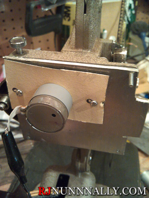
I drilled a hole through the back of the plate I made earlier to allow the film to be viewed. Due to space constraints, the backlight is mounted in the front of the projector where the lens was originally and the image is projected in reverse.
Lens
The lens is now mounted to the rear of the projector. At this stage, the mounting is temporary – as you can probably tell by the zipties. Instead of enlarging the image, the lens now serves as a macro lens providing approximately 1:1 magnification. I’m actually using the original lens for this demo, but I also purchased a new zoom lens from eBay.
Putting it all together
To the left is the current state of the backlight. There are four wires soldered to it – common, red, green, and blue. At full brightness with the resistors I had in my shop, the backlight casts a purple light; this was supposed to be remedied by the Arduino. Indeed, the Arduino is able to control the backlight color – but with visual artifacts, a new solution is needed.
On the right, you can see the lens barrel (far right silver object), the webcam board in the center with the blue power LED, and the projected image itself on the sensor in the center. Remember, this is the bare webcam without any lens at all! It’s all held in temporary place by a “third hand” soldering tool so it’s not in the best alignment.
Below is a wide view of the setup, with the white arrow pointing to the projected image. Here you can clearly see the zipties holding the projector lens in place. Additionally, note that the backlight now casts a warm white light – this is from the adjustment provided by the Aduino.
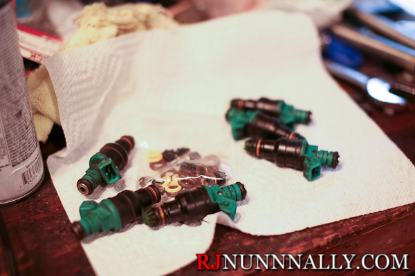
Do your fuel injectors need a refresh? Here’s how to rebuild them.
First, you need to buy a rebuild kit. This will include the filters, o-rings, pintle caps, and spacers required to rebuild your injectors. I bought my kit on eBay. If you just want to replace the o-rings, you can buy a “seal kit” instead, like this one.
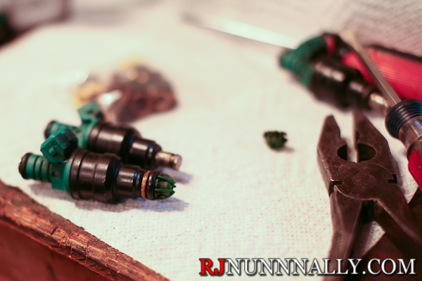
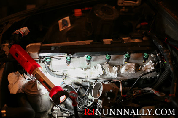
Next, you need to gain access to your fuel rail, pop off any retaining clips if you have them, and then remove the fuel injectors themselves.
BMW M50 Fuel Injectors & Rebuild Kit
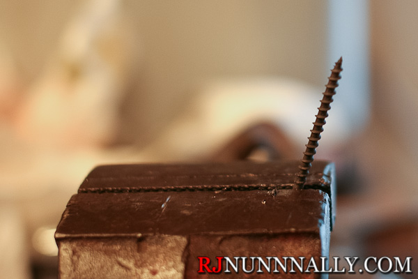
Now mount a wood screw (included in my rebuild kit) that is just large enough to fit inside the injector opening on a vice. Fuel injectors have small, integrated filters inside of them that can clog over time. We will be replacing these filters.
Wood Screw
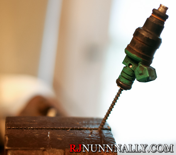
Carefully thread the injector onto the screw until a few threads bite in, then pull the injector away from the wood screw until the filter comes out. This might be difficult.
Fuel injector threaded onto wood screw
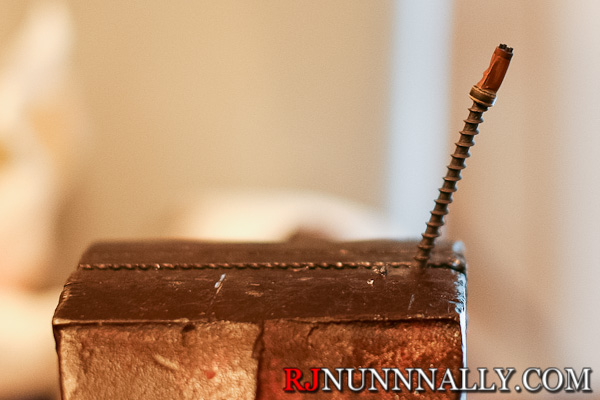
If you are successful, you should see this:
Removed fuel injector filter
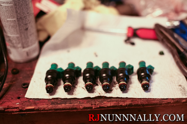
Repeat for all your fuel injectors, in my case 6. At this point, you can optionally clean your fuel injectors using fuel injector cleaner. I may cover this at a later date, but I elected not to clean my injectors this time around. Cleaning is a more complicated process – some people have even built elaborate cleaning rigs to pump fuel injector cleaner through the injectors automatically!
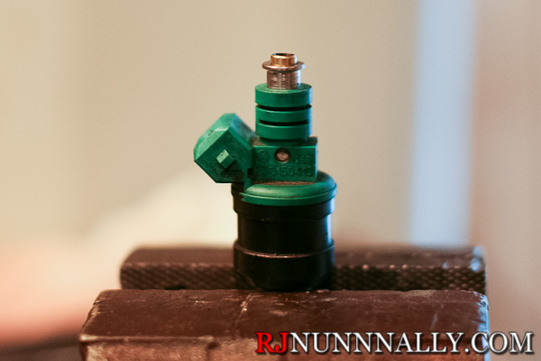
Now *carefully* remove the pintle caps and also remove the o-rings. Do not simply yank the pintle caps off with pliers as it is possible to damage them.
Pintle cap, o-ring, and spacer removed
And then remove the o-ring from the other end.
O-ring removed
Installing the rebuild kit is simple. Start by installing the new filters. They simply press into place – use a tack hammer to lightly tap them in until flush. Then install the top o-ring by rolling it onto the injector. Finish up by installing the spacer (if needed), o-ring, and pintle cap on the bottom of the injectors. The pintle caps easily snap into place and hold the spacer & o-ring on.
Last night saw significant progress on the telecine project. I made a new back for the projector that replaces the original motor & lamp housing, then successfully tested the new DC motor.
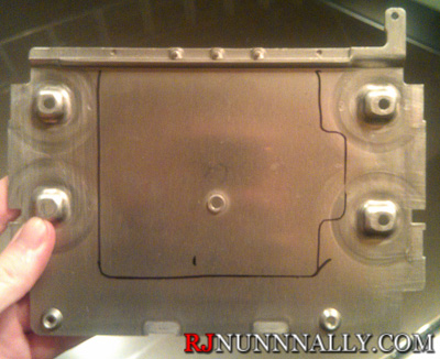
I began with what was once an ECU cover (or more accurately, a DME cover from a BMW). I made a cardboard template of the rear of the projector earlier, than transferred the outline to the cover. From there, I used a dremel to cut the outline out and drilled and tapped four 3mm x .50 holes for machine screws.
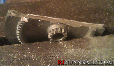
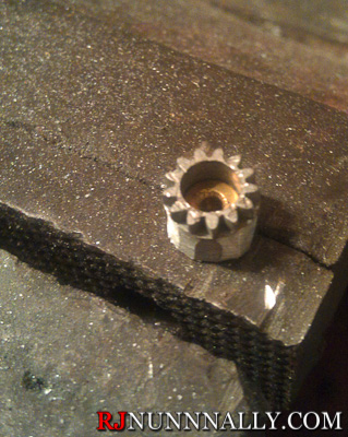
With the plate taken care of, I turned my attention towards the drive gear. The cassette player I sourced the gears from had two identical gears with both inner and outer teeth as pictured. My plans use one of the gears to replace the original drive pulley with the outer teeth being driven. The motor uses the inner teeth of the remaining gear to engage the outer teeth of the now replaced drive pulley, but the gear must be ground down to only the center for it to clear. I used a dremel and grinder to first cut up the gear, then grind the remaining metal down until only the center remained.
The newly ground gear was then mounted to the DC motor. A hole slightly large than the gear was drilled into the new back plate, then the motor was mounted to the back plate. A spacer had to be used for proper clearance, and the spacer also made it easier to mount the DC motor using very shallow screws. With everything mounted, I applied +12v DC to the motor and watched the projector run!